Water Jet Cutting Kerf Width Explained: Factors, Control & Optimization for Precision Cutting
Water jet cutting, a remarkably versatile and powerful machining process, utilizes an ultra-high-pressure stream of water, often mixed with abrasive particles, to cut through a vast array of materials. From delicate composites to thick metals and stone, its cold-cutting nature prevents heat-affected zones, making it indispensable in modern manufacturing. A fundamental characteristic of any cutting process, and particularly critical for water jet cutting when precision is paramount, is the kerf width. This term refers to the width of the material removed during the cutting operation – essentially, the width of the cut path itself. Understanding, predicting, and controlling the water jet cutting kerf width is essential for achieving dimensional accuracy, minimizing material waste, optimizing cutting speeds, and ensuring the overall quality of the finished part. This article delves deep into the intricacies of water jet cutting kerf width, exploring its definition, influencing factors, measurement techniques, implications for design and manufacturing, and strategies for its minimization.
1. Defining Water Jet Cutting Kerf Width and Its Significance
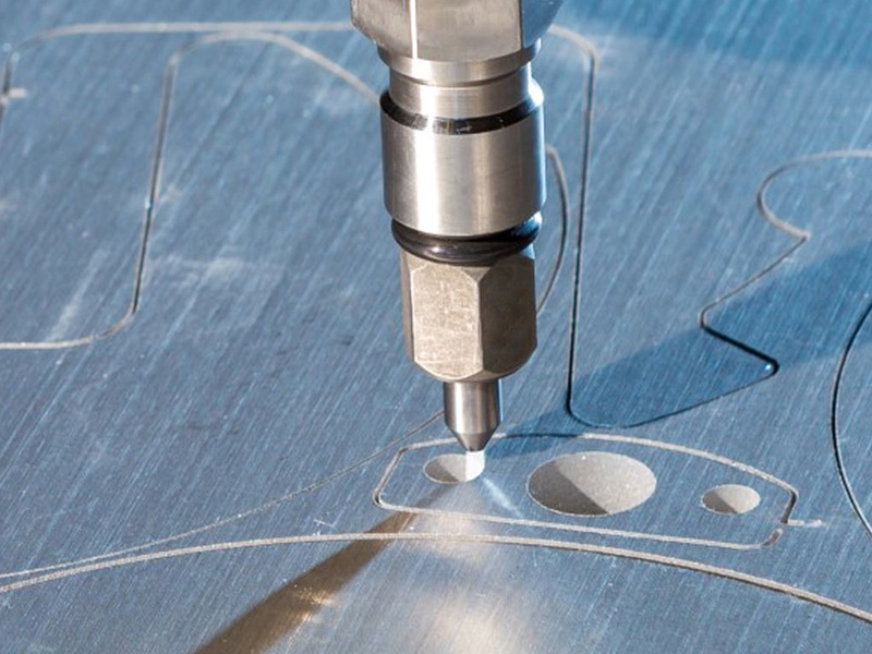
The water jet cutting kerf width is the physical width of the cut slot created by the high-velocity water or abrasive water jet stream as it erodes and removes material. It is not the diameter of the jet stream itself at the nozzle exit, but rather the resulting cut width within the material. This distinction is crucial because the jet stream diverges and interacts with the material as it penetrates, leading to a kerf that is typically wider than the initial orifice diameter.
Why is Kerf Width So Important?
Dimensional Accuracy: The kerf width directly impacts the final size of the cut part. If the kerf is not accurately compensated for in the toolpath programming, parts will be undersized. For intricate geometries or tight tolerances (often required in aerospace, medical devices, or tooling), precise kerf prediction and compensation are non-negotiable.
Material Utilization and Cost: The material lost as kerf represents waste. A wider kerf width means more material is consumed per cut, increasing raw material costs, especially for expensive metals or composites. Minimizing kerf optimizes material yield.
Nesting Efficiency: When arranging parts on a sheet for cutting (nesting), the kerf width determines the minimum distance parts can be placed apart. A smaller kerf allows tighter nesting, further maximizing material utilization.
Cutting Speed vs. Quality Trade-off: Often, parameters that increase cutting speed (like higher traverse rates) can lead to a wider or more tapered kerf, potentially compromising edge quality. Understanding this relationship is key to process optimization.
Feature Detail: The minimum size of internal features (like holes or slots) or the sharpness of corners is fundamentally limited by the water jet cutting kerf width. A smaller kerf enables finer details.
2. Key Factors Influencing Water Jet Cutting Kerf Width
The kerf width in water jet cutting is not a fixed value; it varies significantly based on numerous process parameters and material properties:
Abrasive vs. Pure Water Jet:
Pure Water Jet (PWJ): Used for softer materials (rubber, foam, food, gaskets). The kerf width in PWJ is generally narrower than AWJ but exhibits significant taper (wider at the top, narrower at the bottom). The kerf is primarily influenced by water pressure, orifice diameter, and standoff distance. Kerf widths are typically fractions of a millimeter.
Abrasive Water Jet (AWJ): Used for metals, stone, composites, ceramics, glass. The addition of abrasive garnet (most common) dramatically increases cutting power but also widens the kerf width considerably compared to PWJ. Abrasive flow rate, size, and type become dominant factors alongside water pressure and orifice/nozzle sizes.
Orifice and Focusing Nozzle Diameter:
Orifice Diameter: The sapphire or diamond orifice forms the initial high-pressure water stream. A larger orifice diameter generally results in a wider initial jet stream, contributing to a wider kerf, especially in PWJ and the top of an AWJ cut.
Focusing Nozzle (Mixing Tube) Diameter and Length: In AWJ, the focusing nozzle (mixing tube) confines the abrasive-water mixture. Its internal diameter directly controls the width of the abrasive jet stream entering the material. A larger nozzle diameter produces a wider jet and thus a wider kerf width. Worn nozzles (enlarged diameter) significantly increase kerf and degrade cut quality. Longer nozzles can sometimes provide slightly better collimation but wear faster.
Water Pressure: Higher water pressure (commonly 60,000 psi to 90,000+ psi) increases the velocity of both the water and the abrasive particles. This higher kinetic energy leads to more efficient material removal. While it can allow for faster cutting speeds, it generally results in a slightly wider kerf width due to increased jet energy and potentially more particle deflection within the cut. However, the primary benefit of higher pressure is increased penetration depth or cutting speed for thick materials.
Abrasive Parameters (AWJ):
Flow Rate: Higher abrasive flow rates introduce more cutting particles into the stream, widening the effective cutting diameter and thus increasing the kerf width. Finding the optimal flow rate for a given material and thickness balances cutting speed and kerf size.
Grain Size (Mesh): Larger abrasive grit (lower mesh number, e.g., 80 mesh) removes material more aggressively but creates a wider kerf and rougher surface finish. Smaller grit (higher mesh number, e.g., 120 or 150 mesh) produces a narrower kerf and smoother finish but may cut slower, especially in thick materials. 80 Mesh is standard for general cutting, while 120/150 are used for finer detail and finish.
Abrasive Type and Quality: Garnet is the standard. Higher hardness or density abrasives might influence kerf slightly, but consistency and sharpness are critical. Dull or contaminated abrasive leads to inconsistent kerf and poor cutting.
Traverse Speed (Cutting Speed): This is one of the most significant factors. Slower traverse speeds allow the jet more time to erode material laterally, resulting in a wider kerf width. Faster traverse speeds reduce the lateral erosion time, producing a narrower kerf. However, going too fast leads to incomplete cutting (striation marks, uncut material at the bottom – “lag”) and can increase taper. Optimizing speed is crucial for balancing kerf, quality, and productivity.
Standoff Distance (SOD): This is the distance between the nozzle tip and the workpiece surface. Increasing SOD allows the jet stream to diverge more before hitting the material, leading to a wider kerf at the top surface and increased overall taper. Maintaining a consistent, minimal SOD (typically 0.5mm to 3mm) is vital for kerf consistency and minimizing taper.
Material Properties:

Hardness: Harder materials generally require slower cutting speeds and may exhibit less lateral erosion compared to softer materials cut at the same speed, potentially resulting in a relatively narrower kerf for the same parameters. However, cutting harder materials often requires parameters (like higher abrasive flow) that inherently widen the kerf.
Thickness: Kerf taper becomes much more pronounced as material thickness increases. The top of the cut is always wider than the bottom due to jet energy dissipation and deflection within the kerf. The effective kerf width relevant to part dimensions is often measured at the mid-point or specified based on the critical surface (e.g., top for overlays, bottom for drop-outs).
Homogeneity: Inhomogeneous materials (like composites with resin and fiber) or laminates can cause uneven kerf or unpredictable variations.
3. Kerf Taper: The Inevitable Challenge
A defining characteristic of water jet cutting, especially AWJ on thicker materials, is kerf taper. This refers to the phenomenon where the kerf width is wider at the top surface of the material and narrower at the bottom exit point. Taper is expressed as an angle (e.g., degrees) or a width difference per unit thickness (e.g., mm taper per cm thickness).
Causes of Taper:
Jet Energy Dissipation: As the jet penetrates deeper, its kinetic energy decreases due to friction and interaction with the material and the already-cut walls. Reduced energy means less lateral cutting force at the bottom.
Abrasive Particle Deflection: Particles ricochet within the kerf, losing energy and changing trajectory. Near the top, particles have high energy and deflect widely, eroding more material laterally. Deeper down, particles have less energy and deflect less, cutting more vertically.
Traverse Speed: Slower speeds exacerbate taper because the jet spends more time eroding laterally near the top before finally exiting the bottom. Faster speeds reduce top-width erosion time but can worsen the lag effect.
Implications of Taper:
Taper means the cut edges are not perpendicular. This affects:
Part dimensional accuracy (top vs. bottom dimensions differ).
Fit and assembly of parts.
The ability to achieve sharp, square internal corners.
The visual appearance of the edge.
Managing Taper:
While impossible to eliminate completely, taper can be minimized:
Dynamic Taper Compensation: Advanced CNC controllers adjust the nozzle tilt angle during cutting (lead angle) to counter the natural taper, producing near-vertical walls. This requires sophisticated software and calibration.
Multi-Pass Cutting: Cutting slower on the first pass to establish a straight “pilot” kerf, followed by faster finishing passes.
Optimizing Parameters: Using appropriate pressure, abrasive, nozzle size, and especially finding the optimal traverse speed for the material thickness.
Specialized Nozzles: Research continues into nozzle designs that improve jet collimation.
4. Measuring and Compensating for Kerf Width
Accurately determining and accounting for the water jet cutting kerf width is fundamental for precision manufacturing.
Measurement Techniques:
Direct Caliper Measurement: Cutting a straight line or simple shape (like a circle) and physically measuring the kerf width at specified depths (top, middle, bottom) using calipers or optical measurement tools. This is common but can be subjective and measure only specific points.
Cut Test Samples: Cutting specific test patterns (e.g., comb patterns with varying gaps) designed to reveal the effective kerf width by determining the smallest gap that can be cleanly cut.
Optical Profilometry / Microscopy: Using specialized equipment to create a highly accurate profile of the kerf cross-section, providing detailed width and taper data.
Software Analysis: Some CAD/CAM software for water jet can analyze cut paths and theoretically predict kerf based on known parameters, though physical verification is still essential.
Kerf Compensation:
Once the effective kerf width is known (often an average or specified for a critical surface), it must be compensated for in the CNC toolpath programming. This is done by offsetting the cutting path:
Internal Features (Holes, Slots): The toolpath is offset inwards by half the kerf width. If you program a hole at exactly 10mm diameter and the kerf is 1mm, the resulting hole would be ~11mm. Compensating inwards by 0.5mm produces the desired 10mm hole.
External Features: The toolpath is offset outwards by half the kerf width. Programming a 10mm square without compensation would yield a part slightly smaller than 10mm. Offsetting outwards by half the kerf ensures the part meets the 10mm dimension.
Taper Compensation: Advanced systems incorporating dynamic tilt (lead angle) require compensation algorithms that account for the changing effective kerf width through the material thickness. This is significantly more complex.
5. Strategies for Minimizing Water Jet Cutting Kerf Width
While a certain kerf is inherent to the process, several strategies can be employed to minimize it, particularly when fine detail or maximum material savings are critical:
Optimize Abrasive Selection and Flow:
Use finer mesh abrasive (e.g., 120 or 150 instead of 80) where material thickness and cutting speed allow.
Precisely control and minimize the abrasive flow rate to the lowest level that still provides acceptable cutting speed and quality for the application. Avoid excessive flow.
Ensure abrasive is sharp, clean, and free of fines or moisture clumping.
Utilize Smaller Orifice and Nozzle Diameters:
Employ the smallest practical orifice and focusing nozzle diameter compatible with the material type and thickness. A 0.010″ orifice and 0.030″ nozzle will produce a significantly narrower kerf than a 0.014″ orifice with a 0.040″ nozzle. However, smaller orifices wear faster and require higher pressures for thick materials.
Increase Traverse Speed (Within Limits): As discussed, faster cutting speeds reduce the lateral erosion time, narrowing the kerf. The challenge is finding the maximum speed that still achieves complete cut-through and acceptable edge quality (minimizing striations and lag). High-pressure pumps facilitate faster, narrower-kerf cutting.
Minimize Standoff Distance (SOD): Keep the nozzle as close as safely possible to the workpiece surface throughout the cut. Consistent SOD is crucial. Use height control systems (capacitive or mechanical followers) to maintain optimal distance, especially on warped or uneven plates.
Maintain Equipment in Peak Condition:
Replace Worn Components Promptly: A worn orifice (loses roundness, enlarges) or worn/damaged mixing tube (enlarged inner diameter, flared exit) is the single biggest cause of excessive and inconsistent kerf width. Implement strict nozzle inspection and replacement schedules.
Ensure Clean, High-Pressure Water: Proper filtration prevents orifice blockages. Maintain pump pressure consistency.
Consider Hybrid or Specialized Techniques:
“Deionized” Water Systems: For some pure water applications, deionized water can produce a slightly tighter, more coherent stream.
Ultra-High Pressure (90,000+ psi): Allows for faster speeds with potentially narrower kerf due to reduced interaction time, though initial jet diameter might be a factor.
Specialized Abrasives: Research into novel abrasive shapes or materials sometimes promises narrower kerf, but garnet remains the standard.
The water jet cutting kerf width is far more than a simple measurement; it is a complex and dynamic characteristic central to the precision, efficiency, and cost-effectiveness of the water jet machining process. Understanding the interplay between numerous factors – abrasive use, nozzle geometry, pressure, traverse speed, standoff distance, and material properties – is essential for predicting and controlling kerf. Recognizing and mitigating kerf taper is particularly crucial for thick materials. Accurate measurement and effective compensation in CNC programming are non-negotiable for achieving dimensional accuracy. Finally, implementing strategies like optimizing abrasive parameters, using smaller nozzles, maintaining equipment, and carefully controlling speed and standoff distance empowers manufacturers to minimize the water jet cutting kerf width where needed, unlocking finer details, reducing material waste, and maximizing the value derived from this incredibly versatile cutting technology. By mastering kerf, users truly harness the full potential of water jet cutting for high-precision applications.
continue reading
Related Posts
- 2326 words11.7 min read
- 1452 words7.3 min read


